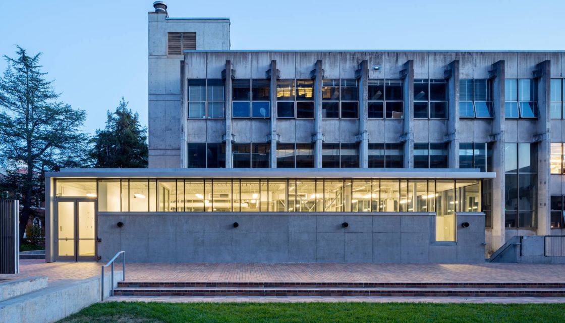
Fabrication + Materials
The College of Environmental Design’s cutting-edge maker spaces and resources — Fabrication Shop, Digital Fabrication Lab, and Materials Store — offer limitless opportunity for students to craft, model, and actualize their studio work.
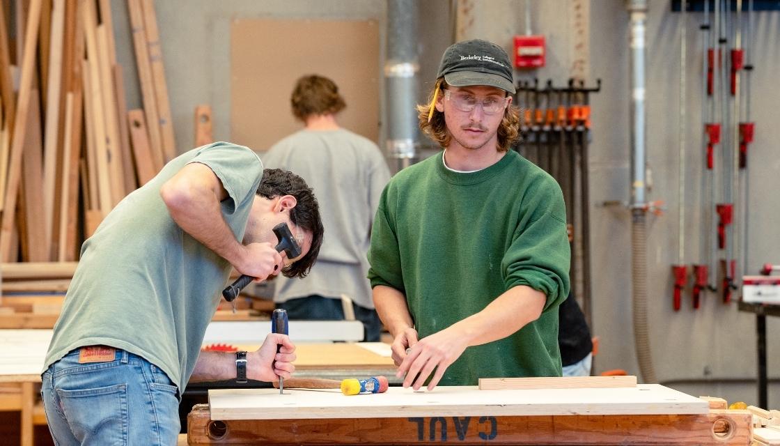
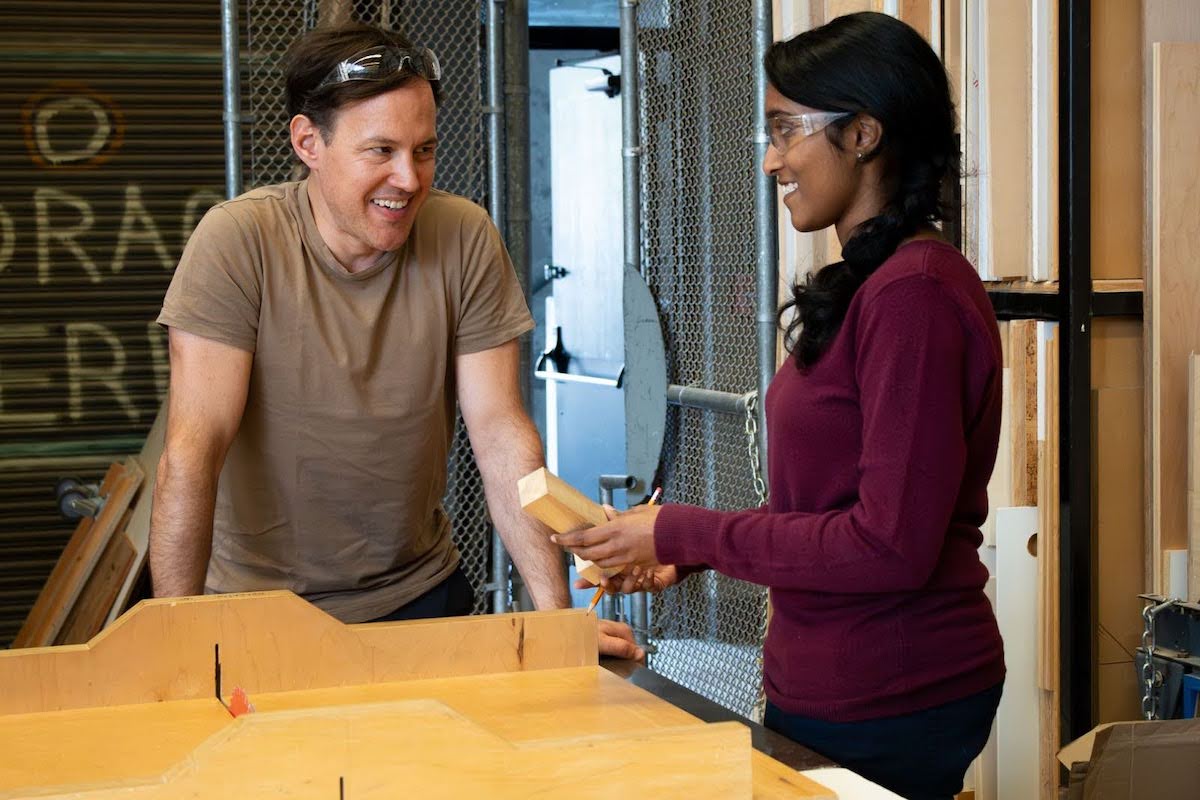
Fabrication Shop

The Fabrication Shop is a 3,600 square foot, open plan industrial wood and metal shop, with a walk-in spray booth and an outdoor shop yard. The wood shop portion has equipment for cutting and milling lumber while the metals portion has equipment for cutting, bending, and welding metal. Students use this space to build models, experiment with new building materials and methods, and process materials so they can be used in our Digital Fabrication Lab. Students are supervised and supported by professional staff, 40 hours a week, for the CED related curricular work.
Digital Fabrication Lab
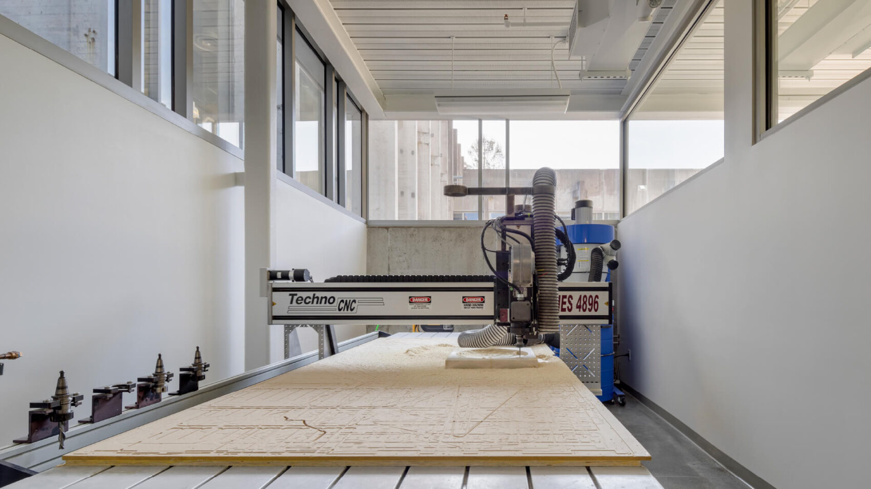
The Digital Fabrication Lab is a 1,500 square foot lab that is home for our laser cutters, 3D printers, and CNC machines. Here, students get the opportunity for hands-on experience operating our machines with the support of professional staff. Students can start with staff consultations to preparing their digital models to cutting or printing their parts on our machines. The seven laser cutters, twenty 3D printers, ShopSabre CNC, and Zund cutting system supports both undergraduates and graduates enrolled in the CED.
Materials Store
Materials Available
The nonprofit Materials Store, provides affordable materials to students (paper, wood, metal, plastic, and casting products) as well as branded items.
Materials include:
- Recycled and reused supplies at very low cost (cutting pads and knives, etc.)
- Solid Wood Lumber
- Plywood
- Plastics
- Metals
- Paper products
- CED branded merchandise
- Small tools and supplies
Purchases can be made with a PaperCut account ($1 minimum) or credit card.
Staff


The Digital Fabrication Lab was funded in part from a bequest from Professor Emeritus Vernon DeMars (BA 1931) and made possible by in-kind donations of design and construction expertise by alum Mark Cavagnero, of Mark Cavagnero Associates Architects, and Tom Mead, formerly of WebCor Builders.